BPCS Loop Failure

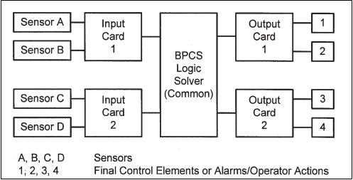
The figure below shows the components of the simplified BPCS Loop. The Final Control Element can be a Control Valve, Shut off Valve, Pump, Relay, etc.
 The important point here is that if any one of these component fails, then the entire loop is disabled and it will not fulfill its function when challenged.

Each component of the BPCS loop has its own failure rate, which, is the function of it's design, manufacture, installation, maintenance, etc. The Probability of the component failing on demand (PFD) is related to it's historic failure rate and it's effective test rate.The PFD for an entire BPCS loop is approximated by summing the PFDs of all its components.

One important point concerning the BPCS Loop failure is their susceptibility to human error. In many installations, the BPCS is delibarately made accessible to personnel who have the ability to change set-points, bypass alarms, etc. This openness while providing operational benefits does leave any BPCS IPLs open to compromise due to human errors.

The PFD Limit stipulated for all IPLs in the BPCS in IEC 61511 does, in a general manner, take account of this factor. Therefore, any method that wishes to take a lower PFD for a BPCS IPL should also consider whether the security of the existing BPCS can support such a change. The security constraints for access to an SIS system are usually far more severe than for a BPCS.
Historical data from a number of companies suggests that, for typical installations, the effective PFD for the BPCS logic solver is at least two orders of magnitude lower than the sensor or final control element of a BPCS loop. When this is true, the probability that the failure of a BPCS loop involved a failure of the BPCS logic solver is no more than approximately 1 in 100 (1 × 10⁻²). In other words, in at least 99 cases out of 100, when the BPCS loop fails, the BPCS logic solver remains fully operational. Any claim for a lower PFD must be supported by internal data or certification by a recognized independent third party.

Approach A:
The failure of any BPCS Loop requires all other BPCS loops using the same Logic Solver (or any other common component) to be considered ineffective. For the same scenario, only one of the loop is allowed to be credited as an IPL (as the Logic Solver is common element).
Approach B:
The failure of any BPCS Loop does not affect other BPCS Loop failure. For the same scenario, both BPCS loops can be credited as an IPL, provided the requirements discussed are satisfied.
Recommended Guidelines for crediting multiple functions in one BPCS Logic Solver for the same scenario
The recommended guidelines for crediting multiple BPCS loops as IPLs for the same scenario are as follows:
• Adequate Access and Security Procedures—These are required to provide assurance that the potential for human error in programming, modifying or operating the BPCS is reduced to an acceptable level.
• Sensor/Final Control Elements—The sensors and final control elements usually have the highest PFD values of all the components in a BPCS loop and are the most likely to cause the failure of a loop.
Sensor(s) and Final Element(s):

No credit can be taken for multiple loops where either the sensor, or the final control element (including action by same alarm and operator response) are common to loops that could otherwise be IPLs for a given scenario or were part of initiating events or enabling events.
In above cases, only one IPL credit can be taken into consideration.
Input Cards/ Logic Solver/ Output Cards
The input and output cards used for transferring information into and out of the logic solver are components that may fail at a higher rate than the logic solver itself. It is recommended that no additional BPCS loops be counted as IPLs where an input or output card is common unless adequate performance can be demonstrated.

Provided all other requirements for an IPL are satisfied, credit would be allowed for a loop with a path of:
Sensor A - Input Card 1 - BPCS Logic Solver - Output Card 1 - Final Element 1Sensor D - Input Card 2 - BPCS Logic Solver - Output Card 2 - Final Element 4
This assumes that both loops meet all the other requirements for an IPL for the same scenario.
The actions of the loops may be either
Two mechanical operations (e.g., shutting a valve, starting a pump) orOne mechanical action and one alarm requiring human action.
Credit should not be taken for two human actions as IPLs for the same scenario unless detailed analysis shows that complete independence can be achieved and both meet the requirements for human action as an IPL.
If the initiating or enabling event involves the failure of a BPCS loop, then no more than one BPCS loop should normally be credited as an IPL for the same scenario.
If human failure is the initiating event then it is not recommended that a BPCS alarm starting human action be counted as an IPL, unless detailed analysis shows that complete independence can be achieved and the operation meets the requirements for human action as an IPL.
If the initiating event is human error and the enabling event does not involve the BPCS, then two BPCS loops can be counted as separate IPLs.
The BP Texas Refinery Incident was a major incident in the Process Industry which involved many failures:
- BPCS Loop Failures
- Operational Procedures
- Maintenance
- Ignorance to previous events
One can find the Investigation Report with details here:
The promotional image used in introduction is copyright content of Yokogawa


